|
|
|
|
|
|
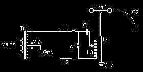
The makers of this page are not responsible for any damage done or harm caused by the use of the information posted on this page. Reading this page is considered to be an acceptance of the risks and hazards associated with Tesla Coils and frees the creators of this page from any liability, whether for physical or emotional harm or damage resulting from improper use of the following information. By continuing to view this page, you automatically accept responsibility for any and all damage done whether from proper or improper use, thus freeing the creators of this page from any and all liability. If you are a minor, parent supervision is suggested. The following is a schematic for a Tesla
Coil
The setup consists of a high voltage AC source, Tr1, which is typically a neon sign transformer powered from a domestic mains supply. This gives a typical output at the secondary of 6 to 15kV, at a few tens of mA and 50 or 60Hz frequency. For a neon sign transformer, the secondary is often centre-tapped. This centre tap is grounded. The a.c. current charges a primary tank capacitor C1 through two safety chokes L1 and L2. The capacitor C1 is of such a low value that during one half-cycle of the 50/60Hz a.c. it will charge to a high enough value that the spark gap g1 will break down. During the discharge at g1 the capacitor C1 is effectively 'connected' to the Tesla Coil Primary L3. The parallel circuit of C1 and L3 (referred to as the Primary Tank) then ocillates or 'rings' until losses dissipate all of the energy. The frequency of oscillation is much higher that the mains frequency, and at this high frequency the chokes L1 and L2 are effectively open circuit. This cycle is repeated on the next mains half-cycle, so that the gap g1 discharges at 100 or 120Hz. L3 and L4 form the air-cored Tesla resonator. L4 consists of a large number of turns of wire, one end of which is grounded, the other of which is connected to a terminal (spherical or toroidal), trm1. The terminal acts as one plate of a capacitor, earth acting as the other plate. This 'stray' capacitance is represented in the above diagram by C2. The combination of L4 and C2 form a similar tuned circuit to the combination of L3 and C1 in the primary circuit. The resonant frequency of the primary circuit is arranged to be the same as the resonant frequency of the secondary circuit. The oscillations of the primary cause the secondary circuit to resonate in sympathy. A very high voltage thus develops on Trm1. Whilst L3 and L4 do behave in some ways as a step-up transformer, it is the resonant effect which contributes most to high voltage seen on Trm1. During operation it is possible for discharges from Trm1 to 'strike' the primary L3. If this high voltage spike were to reach the transformer Tr1 it would be very likely to destroy it. So the combination of L1 and L2 help to filter the voltage spikes, and the 'safety gap' sg1 will fire to dissipate any residual voltage spikes. The high frequencies of oscillation of L3 and C1 can also lead to high dielectric dissipation in insulating materials. As Tr1 is usually only designed to operate at 50 or 60Hz, the high frequencies of operation could cause its insulation to fail. L1 and L2 also help to eliminate this effect. L1 and L2 are typically 2 to 10mH though values up to several hundred mH have been used. Ferrite cored or air cored construction can be used, but a resistor is sometimes required in series with air-cored chokes due to the high Q. It is possible to operate the above circuit with g1 and C1 interchanged. The general consensus is, however, that whilst g1 fires in the above circuit, the radio frequency currents in C1 and L3 cannot work their way back to Tr1 (g1 acting as a short). Variable Transformers (Variacs)The variable autotransformer or Variac (actually a trade name) is a type of transformer having only one winding, instead of two windings found on most standard power supply transformers. They consist of a torroidal iron core on which is wound a single layer winding of copper wire wrapped through the core. The AC line is connected to the ends of the winding. A movable tap is arranged so that it may be rotated around the outside of the coil winding and is able to connect to any turn on the coil. There are two main uses for Variacs in Tesla Coils. The first use is to provide a variable source of AC voltage for the neon transformer. By using the adjustability of the Variac, the voltage output of the neon transformer driving the spark gap can be changed. This allows the coil to be tuned by carefully increasing the power a bit at a time as adjustments are made. When used in this manner, the main AC power line feed is connected across the ends of the Variac winding. The neon transformer primary is then connected between the adjustable tap and one of the connections where the AC power is connected. By adjusting the tap position on the Variac coil, any desired voltage between 0 and 100% of the AC line voltage may be applied to the neon transformer. The second is to act as a current limiter by using the Variac as an adjustable inductor in series with the primary of the neon transformer. When used in this manner, a connections is made to one end of the Variac winding and another connection to the adjustable tap. The third connection is not used. By moving the tap on the Variac winding, more or less turns are included in the coil in the primary circuit of the neon transformer. By using the inductive reactance of the Variac connected in this manner, the maximum current which can flow through the neon transformer at any input voltage setting can easily be adjusted. Manufacturers of Variable Autotransformers are:
Safety GapsDuring Tesla Coil operation the voltages in the primary tank circuit can sometimes be higher than those of the supply. These spurious high voltage spikes are often referred to as Kickbacks. The safety gap is intended as a safety device to prevent damage to the power supply due to kickbacks (usually a neon transformer in low power Tesla Coils). It is not usually constructed to handle the same power as the main gap, as it should only fire occasionally (unlike the main gap). Adjustment of the safety gap is usually by setting the gap so that it only fires occasionally, just enough to protect the supply. This gap spacing should be marginally greater than the main spark gap spacing. For typical neon sign transformer based supplies, of 9 \ 12 or 15kV, a 3/8 inch safety gap is usually adequate. If it does not spark very often, it should be closed up slightly. If it's firing constantly it should be widened slightly. For very high voltage supplies, or very high power levels, there is probably some advantage in using a series of narrowly spaced static gaps for the safety gap. This is because a series of small gaps has a more consistent breakdown voltage from discharge to discharge. Tesla Coil Safety Chokes.Tesla coil chokes are desirable to help isolate the radio frequencies of the primary tank from the power source. In neon transformer-based designs, the chokes help to prevent destruction of the neon transformer's insulation. This is especially important as the primary capacitor in a tesla tank can resonate with the leakage inductance of the neon secondary. The design of the Safety Choke should be such that it 'soaks up' kickbacks or voltage spike that travel from the primary tank circuit back to the power supply (neon transformer). In other words, the Choke should have a low Q factor and should be of a high enough value to act as an open circuit to the high frequency (tens or hundreds of kHz) A.C. voltage spikes. It will, however, act as a short circuit to the lower frequency A.C. supply from the neon transformer (at 50Hz or 60Hz). The value of current flowing through the safety choke is low (unlike the primary tank) so the wire used for winding can be quite thin. The typical Safety Choke is therefore either a ferrite cored choke or air cored Choke of about 2mH value. Air cored chokes can sometimes have too high a Q value, so are usually used with a small amount of series resistance to lower the Q. Some thought should be given to the value of the voltages that will appear across the safety choke. To this end inter-turn insulation needs to be good. If a ferrite core is used this may need some insulation before winding as ferrites are slightly conductive. A suitable thickness of wire is 26 SWG or 26 AWG. An alternative is to strip the braid off a few hundred feet of RG58 RF cable. The inner conductor and its polyethylene insulation are good for winding a Safety choke. Spark GapsThe spark gap can be thought of as a high power high speed switch. The wider the spark gap the higher the breakdown voltage is. No other electronic \ semiconductor device can switch such high power levels as quickly as a spark gap. When the voltage across a spark gap becomes high enough the air between the gap electrodes begins to ionize. Once enough ions build up the gap becomes conductive and an arc jumps the gap. Once the arc occurs the electrical resistance across the gap drops considerably. In fact if the spark gap is thought of as an 'ideal' component the spark gap becomes short circuit. When the voltage across a spark gap falls the ionization decreases and the gap once again becomes an open circuit. Extinguishing of the arc is termed quenching. A gap that quenches well will stop conducting very quickly. To ensure that a gap quenches quickly it can be broken up into a number of gaps connected in series. The heat and ions generated are then spread out over a larger area. If air is blown through the gap this will further improve quenching by helping to remove hot ions that promote conduction in the gap. The multiple gap has a more consistent breakdown voltage than a single equivalent larger gap. The single or multiple connected gaps are often referred to as static gaps. This is to distinguish them from rotary gaps described below. A rotary spark gap is a device that consists of one stationary electrode, and several connected spinning electrodes. The stationary electrode is arranged such that the spinning electrodes pass close to it. The spark gap is then provided by the gap between any one of the spinning electrodes as it aligns with the stationary electrode. This type of gap promotes quenching by the action of the electrodes moving apart. The arrangement has the advantage that some degree of control can be brought over the frequency of discharges. It has the disadvantage that when the electrodes are spaced widely, voltages can rise above those intended. For a series connected set of static gaps, in use with a neon sign transformer based supply, the number and size of electrodes to be used depends on the power level and voltage that the neon sign transformer supplies. The table below can be used as a guide. The electrodes should be made from 22mm (or 3/4") diameter copper tubing, cut to 3 or 4" long. Larger diameter tubing in longer lengths will allow higher power to be used, but 22mm (3/4") tubing is suitable up to 1.5kW. The electrodes should be spaced between .025 and .03 inches apart.
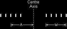
Tesla Coil PrimariesThe Tesla Primary usually consists of a spiral, solenoid, or inverted conical coil of wire or tubing. Tubing is often used because at the frequency of operation of a Tesla Coil current tends to flow over the surface of conductors, so the inner core becomes redundant. Large diameter tubing or wire are used to keep the resistance of the coil low at the operating frequency. Solenoid primaries usually have a diameter that is about two times the diameter of the Secondary, or slightly larger. Inverted conical (or 'Saucer') shaped primaries have a slope of fifteen to thirty degrees. Flat spiral primaries usually have an internal diameter that is two inches or so larger than the Secondary diameter (i.e. a 1 inch gap between the two). Inductance of the Flat Spiral PrimaryThe flat spiral primary is formed from a flat conducting 'ribbon' that is wound into a spiral. A cross section is shown below:
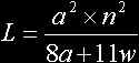
The inductance of this type of primary is given by:
where: L = inductance in microhenries. Grounding of the SecondaryThe Secondary of a Tesla Coil has some similarities with a 1/4 wave antenna. This means that the current at the grounded base of the Secondary is larger than that at the top of the Secondary. So at the base of the coil the current is at a maximum and voltage at a minimum, whereas at the top of the coil the opposite is true i.e. the voltage is at a maximum and the current a minimum. The Ground point should, therefore, be of low impedance to allow the heavy base current to flow to ground. A poor ground will lead to lower voltages at the discharge terminal. The ground lead must have a low inductance, which is often accomplished by using a short heavy flat copper strap connected to one or more large metal stakes driven into the ground. Several stakes in parallel can sometimes outperform one longer stake as a ground. Discharge Terminals (Toroids \ Spheres)The discharge terminal of the Tesla Coil has several functions:
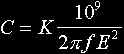
The form that the discharge terminal normally takes is either a sphere or a toroid. The sphere is the theoretical ideal for holding the highest voltages without the surrounding air breaking down, but the toroid gives an electrical field that better protects the top windings of the Secondary Coil. For this reason most Tesla Coils use a toroidal terminal. Ideally the sphere or toroid should be perfectly smooth. This is difficult to achieve in practice. What is important is the relative size of any bumps or imperfections in relation to the overall size of the terminal. So a very large toroid can be built with a few small imperfections. A common material used for constructing an amateur toroid is flexible ducting normally used for clothes dryer vents. This is very common in hardware and home improvement stores. The small corrugations of the vent deviate from the perfectly smooth ideal, but are often ignored because the field created by the overall shape prevents high enough voltage gradients for the surrounding air to break down. For Tesla Coil of 4 inches diameter, which are a popular first choice, 4 or 6 inch diameter ducting is most frequently used. The information below can be used to give an approximation of the capacitance of a toroid.
For a spherical terminal the capacitance may be calculated using the following formula:
Power Factor Correction.Neon sign transformers used for Tesla Coil powers supplies draw current from the a.c. mains that is not in phase with the applied voltage. This is due to the predominantly inductive load that a neon transformer presents to the mains. In other words, the current drawn from the mains LAGS behind the mains voltage, by a phase angle somewhere between 0 and 90 degrees (90 degrees being the worst case). When an a.c. current is not in phase with an a.c. voltage, then Power does NOT equal voltage x current. In fact the current drawn from the mains with a neon powered tesla coil can be much greater than the true power consumption would suggest. This is inefficient as it causes unnecessary losses in the mains wiring. For large banks of neon transformers, the current drawn from the mains can be so high that the mains fuses or circuit breakers will operate. This problem can be resolved with the use of power factor correction (pfc) capacitors connected across the line. The current in the capacitors LEADS the applied mains voltage. The effect is to cancel the inductive LAG and make the net current drawn from the mains be in phase with the voltage. The mains supply then only sees a resistive load. The voltage rating of pfc capacitors should be high enough to cope with the mains voltage, plus an extra allowance for tesla coil use. Local regulations often govern whether a capacitor is of high enough specification to be connected directly across the mains (the so called Y or X rated capacitors). The formula used to determine ballpark pfc is as follows:
Where CORRECTED kVA is determined by dividing the corrected power factor output of the neon sign transformer (Volt-Amps below) by 1000
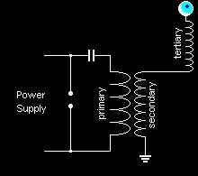
Using a pair of rebuilt 12 kV, 60 ma neon sign transformer, with 2 shunting plates removed from the core next to each high voltage winding, and power factor correction capacitance, you can get a nice 1.5 kVA Tesla power supply with over 90% efficiency. Tesla Receivers.Tesla Receivers are basically free standing tesla coil secondary tuned to the same frequency as the operating tesla coil. The top of a Tesla receiver is connected to a toroid or terminal as with any other Tesla Coil, and the base of the Receiver winding is connected to an RF earth. If the main Tesla Coil has a large enough toroid, it will not break out and will become an RF transmitter. The ground currents will become heavy so a good RF earth is essential. The Tesla receiver will be excited by the transmitted RF and will resonate. Sparks can then be drawn off the toroid of the receiver. The Oudin CoilThe Oudin coil is similar to the Tesla coil except that the inner most turn of the primary and the bottom of the secondary are both connected to ground. Oudin coils often have a characteristic cone shape with the large end sitting on the ground. This configuration almost eliminates the chance of primary to secondary arcing and the loss of energy by corona at the top windings of the secondary coil. Neon sign transformers are not usually used in this way, as only half of the centre-tapped secondary could be connected. The Bi-polar Tesla CoilThe Bi-polar Tesla Coil is a 1/2-wave variation on the Tesla Coil. It possesses the essential tesla coil operational characteristics, but it employs a horizontally placed secondary with discharge electrodes at both ends and a primary at the center. The Bi-polar primary sometimes is merely a pair of taps on the secondary (in effect a resonant autotransformer). The 1/2- wave arrangement affords a coil with maximum discharge at each end and a virtual ground at the midpoint of the winding(s). The Tesla Magnifier.The Tesla Coil Magnifier is a configuration that has primary, secondary and tertiary windings. The primary and secondary work like a conventional transformer, but they are usually air-cored to allow high-power operation at high frequency. The primary and secondary are closely coupled magnetically (coefficient of coupling is 0.4 to 0.6). The primary forms part of a tank circuit (as with the conventional Tesla Coil). One lead from the secondary connects to ground, and the other connects to a 'transmission line'. This line feeds the bottom of the tertiary winding. The tertiary winding is not magnetically coupled to either the primary or secondary. The tertiary is similar to the secondary of a conventional Tesla Coil, complete with top Spherical or Toroidal terminal. The lack of magnetic coupling in the tertiary winding allows it to resonate without its energy being fed back to the spark gap of the primary tank circuit. This is the main advantage of Tesla Magnifiers. The diagram below shows the arrangement.
The close coupling between primary and secondary gives a higher energy transfer efficiency than in a conventional Tesla Coil. The close primary \ secondary coupling has the disadvantage, however, that the spark gap in the primary circuit is difficult to quench. Rotary gaps, therefore, are the spark gaps of choice in magnifier applications. Thanks to Chris Hill for use of his schematics and text |
 Tesla Coil Home Page